


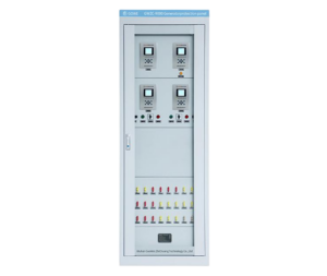
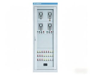
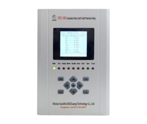
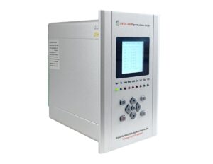
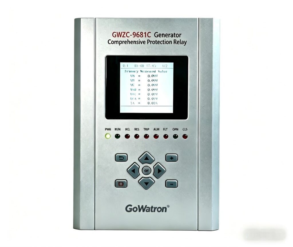
Generator Protection Relay Panel : Composition and Function
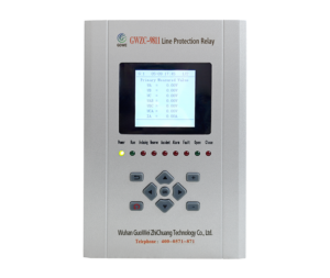
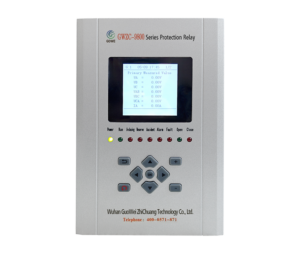
Scope of Application The Generator Protection Relay Panel is mainly suitable for the control and protection of hydraulic units, gas-fired units, biogas units, and large diesel units. Main Components Generator differential protection relay, generator rotor earth fault protection relay, generator backup protection relay, generator measurement and control device, cabinet (2260*800*600 or 2360*800*600) and accessories. Integrating protection, measurement, and communication, the Generator Protection Relay Panel can realize the protection and control of various units, enabling unattended or minimally attended operation. It can achieve generator differential protection, rotor earth fault protection, stator earth fault protection, excitation protection, overcurrent protection, overvoltage protection, overload protection, backup protection, etc. Configuration List of Generator Protection Relay Panel Detailed Functions 1.Generator Differential Protection: Mainly protects against internal faults of the generator. It acts when phase-to-phase short circuits or turn-to-turn short circuits occur inside the generator. 2.Generator Backup Protection: Mainly protects areas outside the generator. Common protection functions include three-stage current protection, negative sequence overcurrent tripping, loss of excitation protection, loss of excitation tripping, stator earth fault zero current protection, stator earth fault zero voltage protection, stator earth fault dual-frequency protection, stator earth fault tripping, reverse power protection, underfrequency protection, etc. 3.Generator Rotor Earth Fault Protection: Divided into single-point earthing and two-point earthing of the generator rotor. Single-point earthing usually triggers an alarm, while two-point earthing requires tripping to disconnect the generator from the power grid. Features 1.The cabinet adopts a size of 2260 (or 2360) × 800 × 600. Each cabinet can be equipped with 3 layers of devices, with 3 devices per layer. Various Protection Relays, as well as automatic control devices, are physically and spatially distributed to the primary equipment bay layer of the main substation. Each device operates as a complete system with an independent power supply, CPU, and independent operating circuit to complete protection, measurement, control, and other functions for the corresponding bay of the power station. All devices are fully independent in software and hardware design and do not rely on the communication network. 2.The CPU chip of the measurement and control device adopts an internationally advanced DSP chip. Multiple software and hardware measures are adopted, such as isolation, software and hardware filtering, watchdog circuit, anti-interference coding, intelligent diagnosis, various opening and closing control circuits, and a new anti-vibration and anti-interference structural design, which improves the reliability of the device. 3.In the communication system, each device can be directly connected to a computer for communication through a field bus, or communicate with a communication management machine. The collected various information is uploaded to the computer monitoring system through the communication management machine; at the same time, the communication management machine transmits the received various commands to the corresponding devices. The control equipment layer takes the primary equipment in the station as the measurement and control object, adopts an object-oriented approach, comprehensively analyzes the requirements of the substation for information collection, processing, and control, and distributes and configures miniaturized and high-reliability microcomputer protection and measurement and control devices. Each device is relatively independent and can communicate with substation-level equipment to realize comprehensive automation of the substation. 4.The protection panel is designed to protect not only the generator but also the excitation transformer, ensuring the reliable and stable operation of the unit, greatly reducing the probability of generator burnout, and providing a strong guarantee for long-term safe operation. 5.The protection panel is equipped with multiple communication and GPS time synchronization ports, all of which are led to terminals, facilitating communication with the power system background, so as to realize remote measurement, remote control, remote signaling, and remote adjustment of the generator by the power system background computer, and collect parameters such as active power, reactive power, current, voltage, frequency, power factor, and electricity consumption.
2025/11/25
Challenges in Miniaturizing 36kV Switchgear
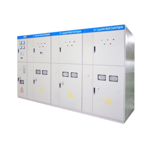
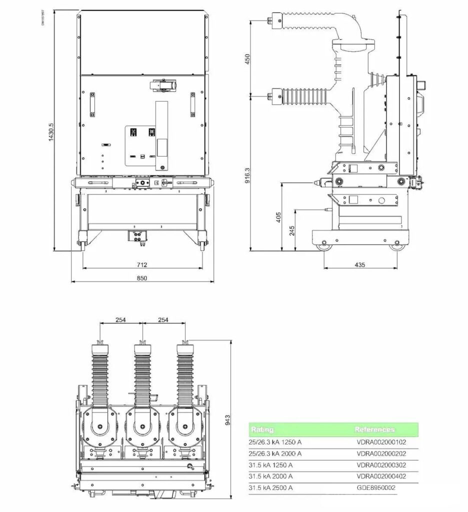
The miniaturization of switchgear is a common demand in the IEC market. For instance, the standard dimensions for 13.8kV (17.5kV), 1250A switchgear are typically 600mm in width and 2100mm in height, while 3150A versions are generally only 900mm wide. However, 36kV air-insulated switchgear typically has a width of 1000mm, with a maximum current rating of 3150A. Some domestic manufacturers use 40.5kV switchgear as a substitute, but these generally have a width of 1400mm, which is often difficult for high-end clients to accept. So, how can we design miniaturized 36kV switchgear? Firstly, it’s essential to clarify the insulation requirements. The rated voltage of 36kV corresponds to a power-frequency withstand voltage of 70kV, which is 74% of the 95kV required for GB 40.5kV switchgear. Its lightning impulse withstand voltage is 170kV, which is 92% of the 185kV required for GB 40.5kV switchgear. This understanding allows for targeted design of the switchgear. Regarding the circuit breaker itself, the typical phase-to-phase distance is 275/300mm, with a pole unit diameter of 200mm. Typically, the circuit breaker chassis width is only 2×300 + 200 = 800mm. For 36kV circuit breakers with smaller phase-to-phase distances, the chassis width can be further reduced. For example, with a phase spacing of 10 inches (254mm) and a wheelbase of 712mm, the switchgear width could be designed as 1000mm, or even smaller. Conventional 36kV circuit breakers feature a phase spacing of 275mm. The breaker poles are fully insulated, and the moving contacts (arms) are solid-insulated all the way to the contact tips, with only the very tips remaining uninsulated. Conventional 36kV circuit breakers have a phase spacing of 275mm. The breaker pole units are fully insulated, and the moving contacts (arms) are solid-insulated up to the contact tips, with only the very tip being uninsulated. The front compartment depth is 1000mm. The breaker rack-in depth is 360mm, which implies a distance of 300mm from the stationary contacts to the shutters. The folding shutter mechanism requires a 30mm travel to open fully. The tulip contacts and stationary contacts have an engagement depth of 30mm. To ensure electrical insulation between the shutters and the stationary contacts, GPO-3 laminated plates are used. These plates have a thin metal sheet pressed in the center, which provides insulation while also meeting the requirements for the PM (Partition Metal-clad) separation type in switchgear. The use of tubular busbars significantly reduces the required clearances in air. Particularly with large-diameter tubular busbars, a tube with an outer diameter of 100mm and a wall thickness of 10mm can carry a current of 3150A. For the RAYCHEM Type BBIT bushing, the phase-to-phase clearance for rectangular copper bars is 140mm, and the phase-to-earth clearance is 190mm. It also very reasonably indicates that the required spacing for round busbars is less than for rectangular bars. When using circular tubular busbars, a phase-to-phase clearance greater than 100mm and a phase-to-earth clearance greater than 160mm are sufficient, provided the air clearance is greater than 320mm. The clearances for tubular busbars can all meet the requirements mentioned above. A larger diameter leads to a more uniform electric field. For instance, with a 3150A, 100mm diameter busbar, the phase-to-phase air clearance is 275 – 100 = 175mm, which is greater than the minimum distance required for heat-shrink tubing. In a 1000mm wide switchgear panel, the phase-to-earth distance is (1000 / 2) – 275 – 50 – 4 = 171mm, exceeding the required 160mm. Regarding temperature rise under high current conditions, the compact switchgear design first leads to shorter copper busbar lengths, resulting in lower heat generation. Secondly, the compact wind channel design facilitates better heat dissipation. Additionally, GPO-3 insulation plates are used on both sides of the cable compartment and between phases within the switchgear, providing dual protection. In the event of an internal arc fault, these GPO-3 plates can also help prevent the arc from expanding and reduce arc exposure to earth. The current transformers used are IEC 36kV type transformers, which have a compact size and their functionality meets the requirements of IEC customers
2025/11/21
What are the common types of low-voltage switchgear?
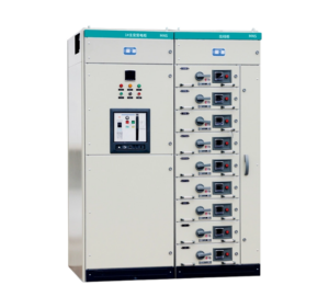
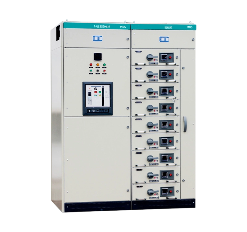
A. International Mainstream Brand Series These series are typically introduced by multinational electrical corporations and are well-known and applied globally. 1.MNS®Series Brand: ABB Characteristics: One of the world’s most famous modular, withdrawable low-voltage switchgear systems. It features a modular design, compact construction, excellent interchangeability of withdrawable units, and high reliability. It is widely used across various industrial, infrastructure, and commercial building applications. 2.Blokset® / Okken® / Prisma® Series Brand: Schneider Electric Characteristics: Blokset: High functionality and flexibility, commonly used in large-scale buildings and industrial projects. Okken: Highly modular and customizable, suitable for industrial and infrastructure sectors. Prisma: A well-established series covering applications from standard to high performance. 3.SIVACON Series Brand: Siemens Characteristics: The flagship low-voltage switchboard series from Siemens, available in both fixed-mounted and withdrawable configurations. It is known for its mature technology and stable performance, and is extensively used in critical power distribution applications worldwide. B. Series Models Prevalent and Widely Used in the Chinese Market These models have become highly mature within the Chinese market, with numerous manufacturers and extensive application cases. 1.GGD Series Type: Fixed-mounted Low-Voltage Switchgear Characteristics: This is one of the most classic and widely used fixed-mounted cabinet types in the Chinese market. It features a simple structure, cost-effectiveness, and easy maintenance. It is suitable for transformer outlets, power and lighting distribution, and is used as incoming, tie, or feeder units. 2.GCK / GCS / MNS Series Type: Withdrawable Low-Voltage Switchgear Characteristics: These three represent the most common types of withdrawable switchgear in the Chinese market. GCK: An earlier technology with a relatively simpler structure and smaller withdrawable units. GCS: A withdrawable cabinet type independently designed in China, featuring a different operating mechanism for withdrawable units compared to MNS, but remains a mainstream product. MNS: As mentioned previously, it is an ABB design. However, due to its widespread use, its design concepts and standards have been adopted and manufactured by many Chinese companies, forming a common category of switchgear. 3.MCCB Distribution Boards / Motor Control Centers (MCCs) Type: Fixed-mounted or Compact Withdrawable Characteristics: This is not a specific series name but a general product category. It typically refers to compact distribution panels using Molded Case Circuit Breakers (MCCBs) as the primary switching devices, used for powering motor loads or for area distribution. They are characterized by a simple structure and small footprint. Summary and Comparison Selection Guidance: For applications with limited budget, simple circuits, and no frequent changes, the fixed-mounted GGD is a cost-effective choice. For applications with high requirements for supply continuity, frequent operation and maintenance, and a large number of circuits (e.g., Motor Control Centers (MCCs) in industrial plants, large commercial complexes), withdrawable types like GCK, GCS, or MNS are preferable. For high-end projects or where specific brands are required, original series from international brands like ABB MNS, Siemens SIVACON, or Schneider Blokset are typically selected.
2025/11/14